
A hidden relic of the past, this 19.2-metre-high concrete well and its 43-metre brick-lined tunnel remain concealed by dense forest near Reservoir Road.

Colemans Tunnel was built by William Frank Oakes around 1882 as part of his contract to build a covered concrete culvert (water race) for £15,000. But the tunnel section was lined with bricks by John Coleman, after whom the tunnel was named. The shaft and tunnel was abandoned by 1902 due to leakage of the water race that led to this tunnel. The race and tunnel were later bypassed with a 30 inch cast iron pipe running from the Lower Reservoir Dam to the existing pipeline at the tunnel’s terminus.
The shaft standing at 19.2 metres (63 feet) high, remains intact today. But its brick-lined tunnel, extending 43 metres, is hidden from public view. In the early 1980s, the tunnel entrance was sealed with bricks and later buried under rocks. Over time, thick scrub and vegetation have completely concealed the site, making it difficult to locate. The tunnel entrance was situated near Reservoir Road with the tunnel going under the road.

The well served as a water conduit, and the attached horizontal tunnel directed the water into a pipe. Beginning at the dam, water flowed along concrete raceway, driven by the weight of the water in the dam and the gravitational force acting on the pipeline. Upon reaching the well, it simply poured down the shaft maintaining a descent. Consequently, when the well reached capacity and potentially overflowed, it served dual purposes.
Coleman’s Tunnel served two key purposes:
Primarily, the shaft provided both volume and gravity-fed water pressure to enhance the flow of water through the pipeline to Wellington. This pressure was essential in allowing the water to reach the Long Tunnel through Wainuiomata Hill and reach Petone.
Secondly, the shaft played a vital role in preventing air from entering the initial section of the sealed pipeline. Air, being compressible, can cause serious issues, generating back pressure and creating hydraulic hammer effects in the system. If not properly managed, these forces could lead to significant damage, including fractures in the pipeline.
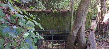 On the western side of the shaft, an outlet connects to a cut channel in the hillside. This was used to divert bywash or overflow when the shaft became full. To control this, the water supply had to be periodically shut off to limit the amount of bywash.
The use of Coleman’s Tunnel was relatively short-lived. After a couple of decades, both the tunnel and its associated water race were replaced by a more efficient pipeline system.
Credits
Special thanks to Jeremy Foster for some information in this article.
Special thanks to Tony Weir for his help with explaining the function of the shaft.


